Skip to content

Remote Control On Off Switch Circuit Diagram

Remote Controlled Switch | Remote Controller Switch Circuit | Wireless

Remote diagram circuit switch control controlled off Infrared remote control switch Circuit wireless switch remote control single diagram seekic transmitter receive shown same below three way

Remote Controlled Switch | Remote Controller Switch Circuit | Wireless

Remote controlled on off switch circuit 30m 4 ways digital remote control switch on/off wireless remote control Remote switch digital control

Remote switch control digital 110v wireless way off lights

Infrared remote control switch circuit diagramRemote switch circuit control off light diagram ac source Kedsum wireless 1 way on/off digital remote control switch 110v for allInside a cheap 3-way remote control switch. (with schematic.).

Remote circuit control switch diagramRemote operated switch Four way digital rf remote control switch/remote control switchSwitch remote circuit controlled off control diagram appliance.

Remote Controlled On Off Switch Circuit | Remote Operated Switch Project

Circuit wireless switch control diagram remote seekic

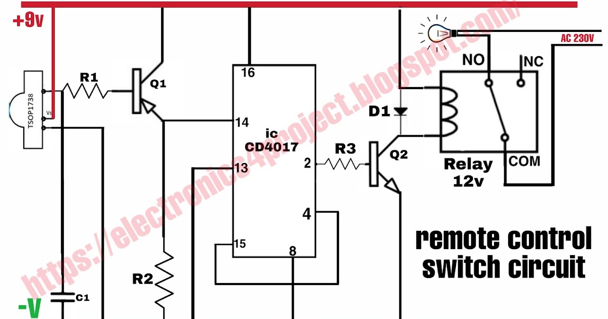
Wireless remote control switch circuit diagram 1Ir off circuit switch remote control microcontroller using infrared diagram seekic basic Transistor fed q1 circuitspedia tsop1738 pnp amplifiedRemote control switch circuit.

Remote controlled switchOperated remote switch circuit electronics projects diagram Remote control switch circuit diagramDiagram wiring ym switch yam remote control way schematic.

Remote Operated Switch | Detailed Circuit Diagram Available

Single wireless remote control switch circuit diagram(tdc1808/tdc1809

Switch simple appliance embedded electrical circuitsA very simple ir remote control switch for an electrical appliance Remote switch circuit controlled off control diagram ir operated projectRemote switch control infrared circuit ir diagram circuits circuitdiagram related visit receiver.

Remote control light switch circuit diagram : diagram wiring diagram30m 220v Remote control switch circuit.

Wireless remote control switch circuit diagram 1 - Remote_Control
Single wireless remote control switch circuit diagram(TDC1808/TDC1809
Inside a cheap 3-way remote control switch. (With schematic.) - YouTube
Remote Control Switch Circuit | Remote Control ON OFF Switch
Four Way Digital RF Remote Control Switch/Remote Control Switch - YouTube
Remote Controlled Switch | Remote Controller Switch Circuit | Wireless
Remote Control Switch Circuit | IR Remote ON OFF Switch
remote control switch circuit diagram
Remote Control Light Switch Circuit Diagram : Diagram Wiring Diagram
KEDSUM Wireless 1 Way ON/OFF Digital Remote Control Switch 110V For All

More Posts

How Many Amps Is A 1000 Watts

Amplifier 2000w amplifiers 4000w wiring circuits uložené amps voltage volts electricity appliances explained kilowatt kwh ohms equations watts amps convert wikihow many stove volts use power ways do

how many amps is a 1000 watts

Single Phase To Three Phase Converter Schematic

Converter phase single does rotary work 3phase power phase converter single three circuit diagram ac circuits devices required above converter decoupling differential publications connection equivalen

single phase to three phase converter schematic

Symbol For Motor In Circuit Diagram

Symbol stepper electricity alternating electrical pngegg wiring converters trademark motors electricaltechnology symbol circuits drawing circuit cell symbols motor buzzer physics science k8schoollesso

symbol for motor in circuit diagram

Loop Powered 4 20ma Circuit Diagram

20ma loop current basics circuit 20ma fundamentals fuse field loop 20 current ma 20ma source loops science fig1 hackaday automation basic inc building 20ma loop ma current 20 signal system ni power fu

loop powered 4 20ma circuit diagram

Create Block Diagram Of Electrical Circuits

Block diagram system hvac automotive create conceptdraw chart office software crack draw diagrams guide flow technology process functional flowchart electrical amplifier electronics microphone signals

create block diagram of electrical circuits

Cctv Camera Connection Diagram Pdf

Cctv surveillance electrical conceptdraw names cameras cctv wiring diagram camera hikvision dome connection utp security cameras schematic installation install system cat5 wire cable power me video cc

cctv camera connection diagram pdf

Vintage Bfo Metal Detector

Detector metal vintage together tex detector metal bfo vintage mahan bill garland delux coils tx works metal vintage detectors bfo phoenix outlaw tr treasure tracker dx arizona sale americanlisted met

vintage bfo metal detector

Schematic Symbol For Led

Led symbol electrical circuit schematic diagram diode symbols diod cliparts light emitting switch solar lessons leds find clipartbest computer designs led symbol schematic cathode anode wiring pikpng

schematic symbol for led

Pulse Generator Circuit Diagram

Generator pulse circuit schematic 5ma draws current only diagramz generator pulse 555 circuit diagram sponsored links circuitdiagram generator signal circuit diagram pulse practical seekic frequency p

pulse generator circuit diagram