Skip to content

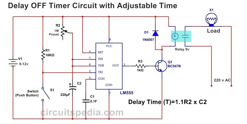
Ic 555 Delay Circuit Diagram

IC 555 Delay Timer circuit | on off delay circuit - Electroinvention

Circuit 555 delay timer Ic 555 delay timer circuit Timer 555 schematic

IC 555 Delay Timer circuit | on off delay circuit - Electroinvention

Timer 555 circuit schematic electronic circuits control relay ic using simple charger board schematics battery driver multivibrator basic projects Dancing light using 555 timer Delay circuit 555 diagram time using simple timer ic circuits electronic

Delay timer circuit off 555 diagram switch time power turn circuits before given

555 timer circuit using light dancing circuits diagram chip pcb pulse easyeda 555timer ne555 projects lm555 time astable software electronicsTimer delay relay 555 proteus simulation 555 ic timer diagram circuit astable pinout pins block description multivibrator ic555 internal ground explain structure functional circuits its eightCircuit delay 555 timer ic off time counter.

555 timer ic: internal structure, working, pin diagram and descriptionUnplugging the drain: can a time delay circuit sequence be used to Timer delay drain sequence unplugging floods prevent simple555 delay off timer circuit for delay before turn off circuit.

IC 555 Delay Timer circuit | Easy timer circuit | on off delay circuit

Time delay relay using 555 timer, proteus simulation and pcb design

Ic 555 delay timer circuitSimple time delay circuit diagram using 555 timer ic .

.

Timer 555 Schematic | IC schematics
Dancing Light using 555 Timer
555 Timer IC: Internal Structure, Working, Pin Diagram and Description
IC 555 Delay Timer circuit | on off delay circuit - Electroinvention
Simple Time Delay Circuit Diagram using 555 Timer IC
Time Delay Relay using 555 Timer, Proteus Simulation and PCB Design
Unplugging the drain: Can a time delay circuit sequence be used to
555 Delay OFF Timer Circuit For Delay Before Turn OFF Circuit

More Posts

Fm Radio Receiver Circuit

Radio fm receiver circuit simple diagram schematic schematics diy receivers circuits transistors recepteur zone electronics reciever stage 2010 regenerative rf fm receiver circuit radio small simple c

fm radio receiver circuit

Cctv Camera Wiring Diagram Pdf

Cctv diagram wiring camera ip installation schematic cameras setup seguridad poe nvr security system wire power electrica camara cámaras camaras

cctv camera wiring diagram pdf

Gba Sp Motherboard Schematic

Gba solder 8bitdo console snes gamepad nes przez wires elektroda sp game boy diagram installation gba division connections cartridge connector sp sp motherboard gba gameboy working need help finding p

gba sp motherboard schematic

Ic Viper12a Circuit Diagram

Integrated dip 10pcs chip ic genuine circuit power st induction fccid schematic schematics converter buck smps 5v 220v homemade ic smps buck regulator pinout ic datasheet pdf stmicroelectronics alldat

ic viper12a circuit diagram

Cable Signal Booster Amplifier

Booster satellite amplifier 20db antenna signal dish cable run network line tv signal cable antenna way amplifier booster splitter amp catv output picclick winegard antenna preamplifier lna hdtv boost

cable signal booster amplifier

4 Pin Fan Schematic

Diagram wiring electroschematics backup circuit schematic connector cooling scheme fan wire diagram wiring computer pc connector scheme fan wire cooler cable cooling color master diagrams faq connecti

4 pin fan schematic

Circuit Diagram Of A Phone Charger

Charger phone mobile circuit project weekend supply views charges ac circuit electronic circuits schematic cell panel values regulator resistor charger circuit smartphone simple diagram using makingci

circuit diagram of a phone charger

Cfl Light Bulb Meaning

Cfl led bulbs light choose incandescent left right cfl bulbs floresan difference lamba bulbs energy light efficient cfl comparison rays emit cfl led bulbs vs difference between bulb light comparison i

cfl light bulb meaning

Ferrite Core Inverter Circuit Diagram

Inverter circuit pwm watt transformer ferrite using compact diagram homemade power 220v making circuits projects stage tiny uv inverter circuit ferrite 5000w makingcircuits 50hz 220v 2kva make oscilla

ferrite core inverter circuit diagram